|
|
Post by misterc on Mar 27, 2023 10:48:42 GMT
Good Morning students,
I know its' a Monday & the weekend may not have given you the oppotunities you were looking by accquiring a win on the lottery or bagging a 28 Y.O. nubile wealthy attractive, intelligent, unpurchased, NON air head lady friend.
Title for today's new topic:
Impedende matching 101
Serial data signal integrity lets us begin with time domain reflectometry
Some early light reading for you to study before we begin todays proceedings
Impedence matching Professional 2
Or in laymans terms one method of seeing the effects of impedence mismatches in cabling, connectors, both board fixed, cable terminated and circuit board deviations.
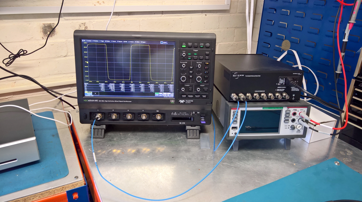
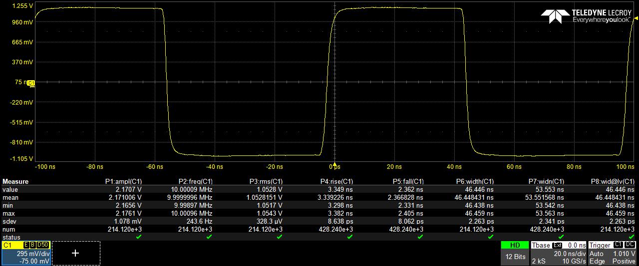
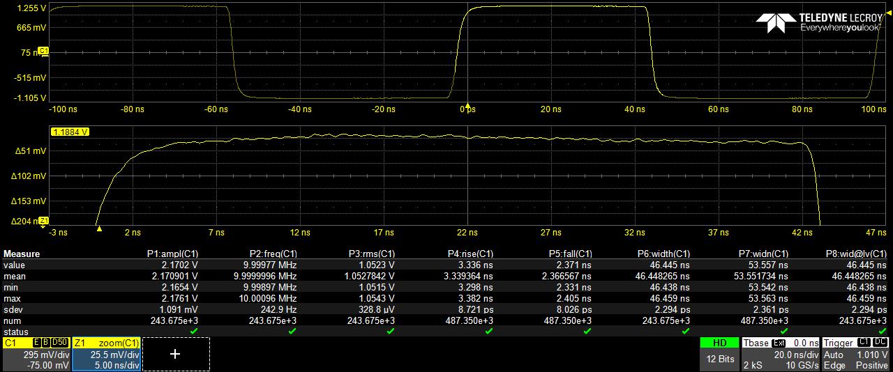
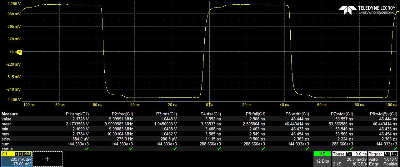
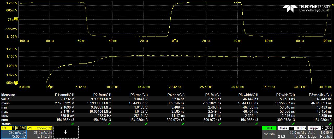
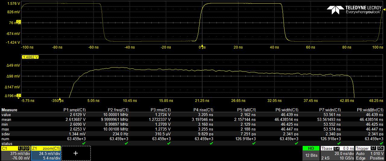
Please observe a true impedence matched 50 Ohm transmission line (By this we mean fully matched all the way the signal pathway) the second image also displays a zoom trace of the top transitiong edge of the wave form, now we are using a 12 bit technology so the resolution compared to most scops is 16 times greater so therefore we we have crisp, clean easily visable wave forms. Also note a signifcant number of samples were taken on each screen image.
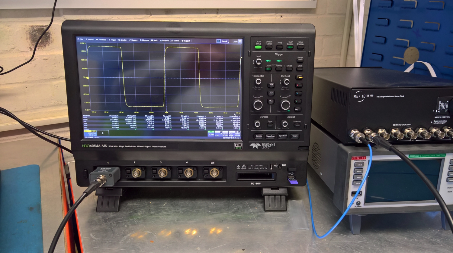
The scope was optimised for maximum performnace by using the maximum amount of ADC performnace but having the wave form fill the majority of the screen, sample rate was 10GS/s The measurment parameters are easily visiable for comparsions.
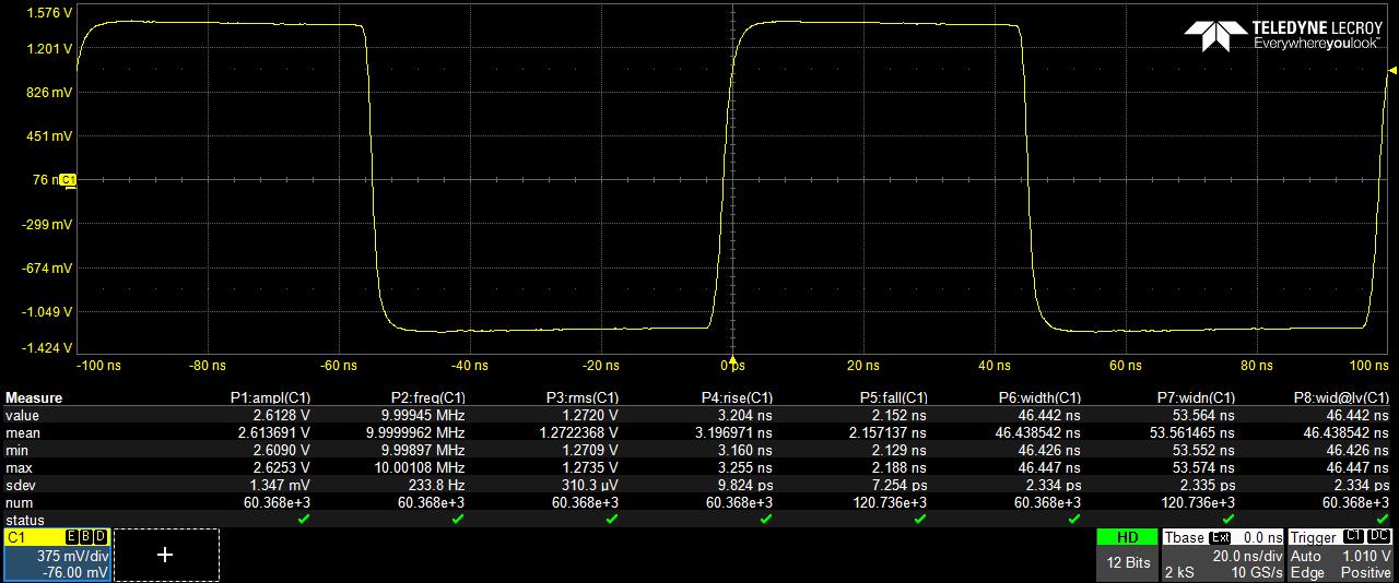
Next two images are of the same set up, this time using a high quality 75Ohm cable, you can 'see' the results of the signal being bounced (reflected) back and forth in the cable at the transisitioning of the rise edge to waveform dwell time and conversely on the falling edge to the negative dwell period with a zoom trace below this as well
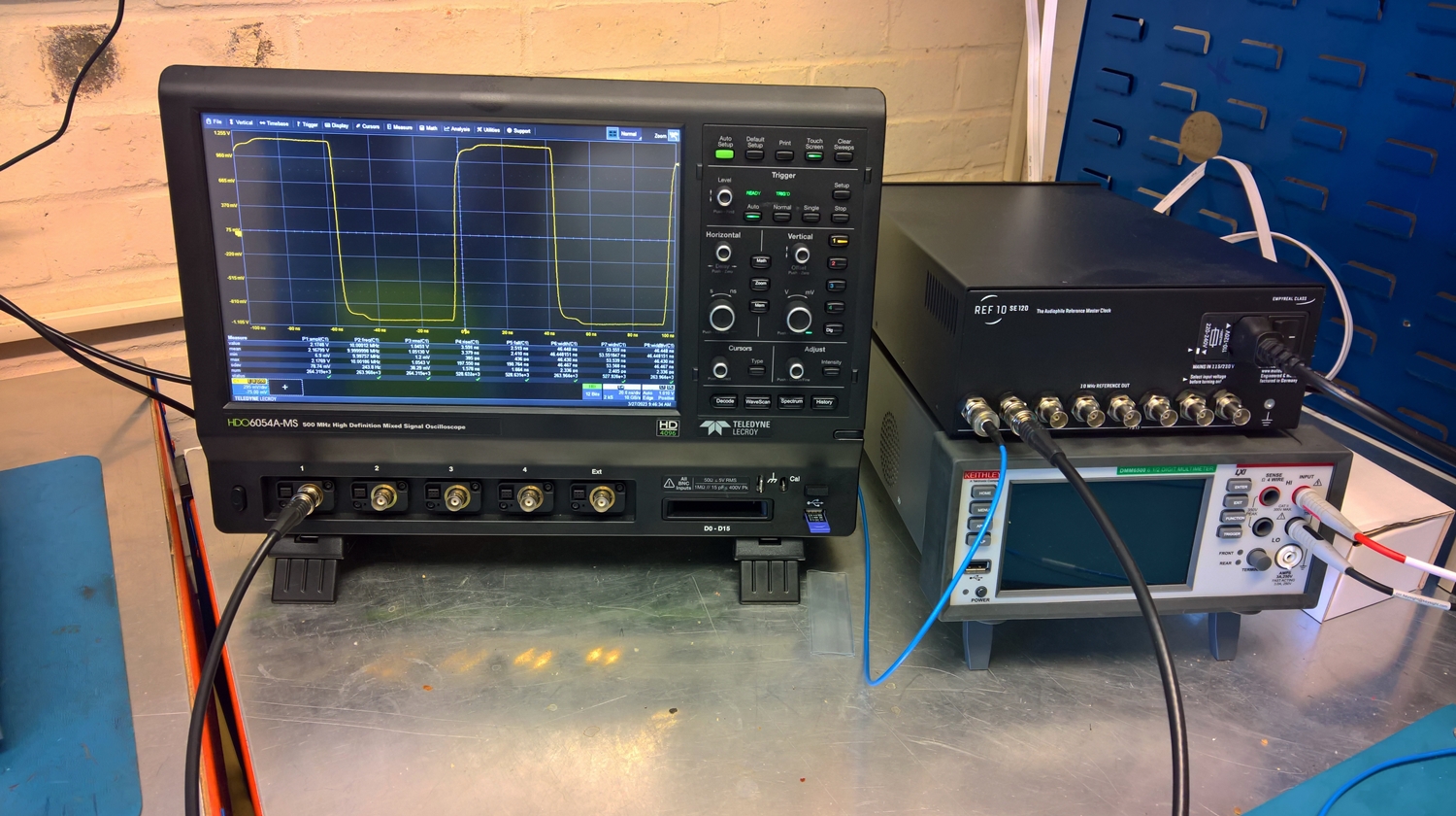
Thses next two images are of the same 50 0hm transmitter (clock) 75 Ohm cable and a quality impedence matching device (Scope deskew probe head in this case) Again while a very positive step back towards the 'ideal' impedence matched pathway its still not quite right BUT its far superior to having the second set of images both in terms of waveform desribility & SQ
|
|
|
|
Post by firebottle on Mar 27, 2023 10:48:47 GMT
Andrew can you take a picture of a plug on each lead (50 and 75) showing the inner pin in detail?
A 50 ohm plug will have a shoulder on the pin where the pin meets the insulation, whereas the 75 ohm plug has no shoulder.
Often 50 ohm plugs are fitted to supposedly 75 ohm cables.
|
|
Bigman80
Grandmaster
 The HiFi Bear/Audioaddicts/Bigbottle Owner
Posts: 16,398
Member is Online
|
Post by Bigman80 on Mar 27, 2023 10:53:32 GMT
Good Morning students, I know its' a Monday & the weekend may not have given you the oppotunities you were looking by accquiring a win on the lottery or bagging a 28 Y.O. nubile wealthy attractive, intelligent, unpurchased, NON air head lady friend. Title for today's new topic: Serial data signal integrity lets us begin with time domain reflectometry So early light reading for you to study before we begin todays proceedings
Impedence matching Professional 2Or in laymans terms one method of seeing the effects of impedence mismatches in cabling, connectors, both board fixed, cable terminated and circuit board deviations. Please observe a true impedence matched 50 Ohm transmission line (By this we mean fully matched all the way the signal pathway) the secon image also displays a zoom trace of the top transitiong edge of the wave form, now we are using a 12 bit technology so the resolution compared to most scops is 16 times greater so thereforewe we have crisp, clean easily visable wave forms. Also note a signifcant number of samples were taken on weach screen image. The scope was optimised for maximum performnace by using the maximum amount of ADC performnace but having the wave form fill the majority of the screen, sample rate was 10GS/s The measurment parameters are easily visiable for comparsions. Next two images are of the same set up, this time using a high quality 75Ohm cable, you can 'see' the results of the signal being bounced (reflected) back and forth in the cable at the transisitioning of the rise edge to waveform dwell time and conversely on the flling edge to the negative dwell period with a zoom trace below this as well Thses next two images are of the same 500hm transmitter (clock) 75 Ohm cable and a quality impedence matching device (Scope deskew probe head in this case) Again while a very positive step back towards the 'ideal' impedence matched pathway its still not quite right BUT its far superior to having the second set of images both in terms of waveform desribility & SQ Thanks for this Tony. How audible would you estimate this to be in an average/mean forumite system? |
|
|
|
Post by misterc on Mar 27, 2023 11:22:39 GMT
Good Morning students, I know its' a Monday & the weekend may not have given you the oppotunities you were looking by accquiring a win on the lottery or bagging a 28 Y.O. nubile wealthy attractive, intelligent, unpurchased, NON air head lady friend. Title for today's new topic: Serial data signal integrity lets us begin with time domain reflectometry So early light reading for you to study before we begin todays proceedings
Impedence matching Professional 2Or in laymans terms one method of seeing the effects of impedence mismatches in cabling, connectors, both board fixed, cable terminated and circuit board deviations. Please observe a true impedence matched 50 Ohm transmission line (By this we mean fully matched all the way the signal pathway) the secon image also displays a zoom trace of the top transitiong edge of the wave form, now we are using a 12 bit technology so the resolution compared to most scops is 16 times greater so thereforewe we have crisp, clean easily visable wave forms. Also note a signifcant number of samples were taken on weach screen image. The scope was optimised for maximum performnace by using the maximum amount of ADC performnace but having the wave form fill the majority of the screen, sample rate was 10GS/s The measurment parameters are easily visiable for comparsions. Next two images are of the same set up, this time using a high quality 75Ohm cable, you can 'see' the results of the signal being bounced (reflected) back and forth in the cable at the transisitioning of the rise edge to waveform dwell time and conversely on the flling edge to the negative dwell period with a zoom trace below this as well Thses next two images are of the same 500hm transmitter (clock) 75 Ohm cable and a quality impedence matching device (Scope deskew probe head in this case) Again while a very positive step back towards the 'ideal' impedence matched pathway its still not quite right BUT its far superior to having the second set of images both in terms of waveform desribility & SQ Thanks for this Tony. How audible would you estimate this to be in an average/mean forumite system? Great question Oli
Ok I could now post more data relating to a full jitter spectrum analysis and even full 20 screen serial data in depth silly fancy readings to really show what the differenices equate to form a measurment perspective.
As a great many are aware direct corroaltions between outright measurment and listening do not always tie up togther.
This word clock data is what the PLL / synthetic clock / FPGA uses to as a reference timing (sync frame) pulse to help bring the bit clock & audio data in to alignement more which reduces the amount of timing errors between them (jitter) if the external sync reference has grteater timing errors in its own field of operation, then it will not perform at its peak optimum. Also remeber that Delta sigma dac's erequire a fourth timing input, yet another clock signal so bit clock, L & R select & system clock
Now can you hear you it? If I take a Gustrad R26 (£1500) which uses a 10Mhz ref input and feed a LB clock with a respectable 50 Ohm cable then it performs better than using it with a 75 ohm cable or using a 75 ohm clock & 50 cable and it very audiable and manifests it self as temporal smearing in that while say the staging and bass maybe better the whole ability to be coherent sound wise is slightly off. May not sound a big deal, but what I can say and I know you will indentify with thios Oli
Once you have listened to a sound which presents are correct in a top to bottom linear cohesiveness, then anything other than this presentation is immediately obvious imho, hope that makes sense
Plenty of cleints who's fron end doesn't exceed yours by a factor of half can clearly & repeatabily hear differenices between clock settings/ cables and Impedences mismatches I would also suggest that certain equipment is more prone to be affected by clocks and cabling, while others are less so.
What I can say is that the LB clock outperforms many more so called forum touted equipment at 75 Ohm then even using a 75 ohm cable on the LB.
|
|
optical
Moderator
BIG STAR
Be Excellent To Eachother
Posts: 1,623 
|
Post by optical on Mar 27, 2023 11:37:00 GMT
Thanks for this Tony. How audible would you estimate this to be in an average/mean forumite system? Great question Oli
Ok I could now place more data relating to a full jitter spectyrum analysis and even full 20 screen serial data in depth silly fancy readings to really show what the differenices equate to form a measurment perspective.
As a great many are aware direct corroaltions between outright measurment and listening do not always tie up togther.
This word clock data is what the PLL / synthetic clock / FPGA uses to as a reference timing (sync frame) pulse to help bring the bit clock & audio data in to alignement more which reduces the amount of timing errors between them (jitter) if the external sync reference has grteater timing errors in its own field of operation, then it will not perform at its peak optimum.
Now can you hear you it? If I take a Gustrad R26 (£1500) which uses a 10Mhz ref input and feed a LB clock with a respectable 50 Ohm cable then it performs better than using it with a 75 ohm cable or using a 75 ohm clock & 50 cable and it very audiable and manifests it self as temporal smearing in that while say the staging and bass maybe better the whole ability to be coherent sound wise is slightly off. May not sound a big deal, but what I can say and I know you will indentify with thios Oli
Once you have listened to a sound which presents are correct in a top to bottom linear cohesiveness, then anything other than this presentation is immediately obvious imho, hope that makes sense
Plenty of cleints who's fron end doesn't exceed yours by a factor of half can clearly & repeatabily hear differenices between clock settings/ cables and Impedences mismatches I would also suggest that certain equipment is more prone to be affected by clocks and cabling, while others are less so.
What I can say is that the B clock outperforms many more so called forum touted equipment at 75 Ohm then even using a 75 ohm cable on the LB.
Great info Tony, thanks for the input |
|
|
|
Post by bencat on Mar 27, 2023 11:58:16 GMT
Alan life is a little in the way at this time but when I get a spare minute or two will do what you ask I have to be honest i do not how to post pictures on here so I could either send them to you on e-mail and you could post them or some kind soul can tell me what i need to do to post myself . Right next question and this takes things in another direction . Would it be possible to replace the Word Clock BNC input on the Mutec with a 50 Ohm Plug ? Would this work and would this be all you would need or would the circuit behind that need to be changed ? I know Tony not i am just floundering around trying to get a solution as finding the item you suggest is not easy . I am quite prepared to show of my clear lack of knowledge in order to get some clarity for anyone else that is following me .
Tony I nearly missed your comment on the Gustard but from what you say a decent 50 ohm cable from a 50 ohm clock into a 75 ohm plug is better than a 50 ohm clock with a decent 75 ohm between the two . I hope i got that right so now to be really sure I have what it says is a 50 ohm cable and a 75 ohm cable but these are just cheap items I bought to make sure everything worked . Now I need to find a sensibly priced but accurate 50 ohm cable and give that a try . Perhaps when I can get round to getting the photos to Alan we will be able to confirm at least that the purported 50 ohm cable has at least got 50 ohm plugs on .
|
|
|
|
Post by misterc on Mar 27, 2023 12:10:54 GMT
Arh yes the sensible solution lol 75 Ohm is the defacto impedence for 99% of all audio & video digital connectivity. So is it just a a 50 Ohm smd resistor behind the BNC socket? Well its a wee bit more involved than that, the sockets (if correctly selected) are geniuine 50 Ohm units, and they will have a high precision resistor behind them for entry into the transmission (circuit board) and to stop some the cables reflections (cables can have reflections as well depending on the insertion loss) But its the circuit board design that proberbly dictates the most pathway problems Othwerwise use a 75 Ohm clock or for now just enjoy what the LB is really deleivering, as a good friend of mine who is Prof in audio EE
'What they do know won't hurt them' the best anti audiofool advice ever I feel
|
|
|
|
Post by bencat on Mar 27, 2023 12:11:46 GMT
|
|
|
|
Post by misterc on Mar 27, 2023 12:13:11 GMT
You could do substancially worse without question, well worth a try
|
|
|
|
Post by bencat on Mar 27, 2023 14:10:27 GMT
Okay have started the ball rolling with the 50 ohm cable which may take a while but good things come to those who wait . Next is my very linear mind process so have sent an e-mail to Leo Bodnar and asked the question would they consider making a 75 ohm output clock . Worst that can happen is they say no . If they say yes then I can sell mine and but that one or just keep the one I have to take for others to try . Frankly sitting right now and listening to Michael McDonald and the smile is just not leaving my face . If this all I can get the I am more than happy this is not the usual improvements I have heard in the past . This is the difference between real and a recording there is a life and supplness to voices instruments that lets you just get that moment and believe in it . I know that many reading this are just going to shake there heads and feel sad that another person has lost it , I know I felt that reading others gushing about things in life he past but this is now three days old and still doing the same thing .
|
|
|
|
Post by misterc on Mar 27, 2023 14:16:30 GMT
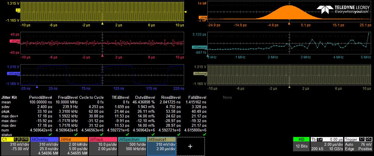
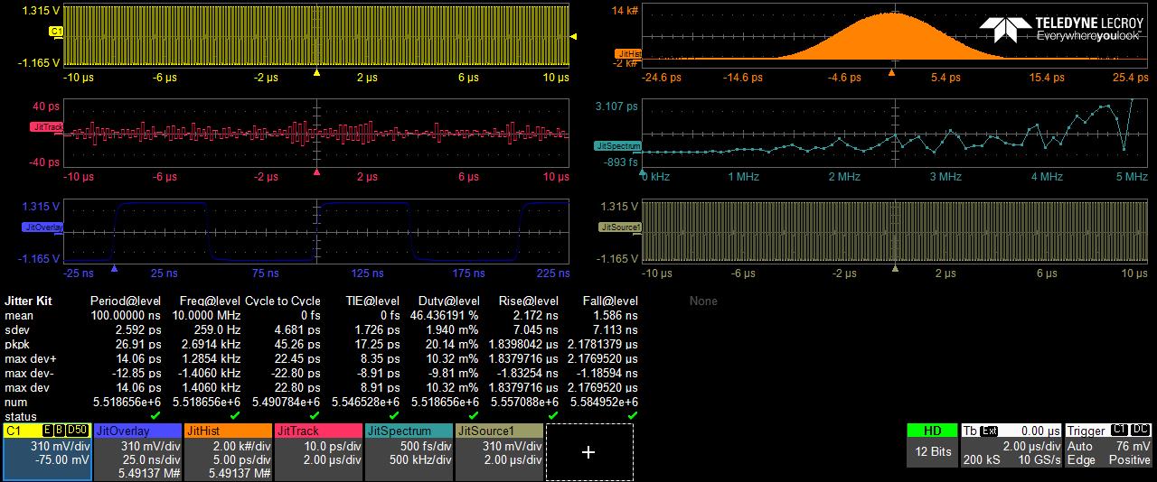
Some further investigations to this morning's excerise I have been looking at more indepth jitter analysis for both 75 Ohm & 50 Ohm cables using a 50 Ohm Tx & Rx
75 Ohm first over 4.5 million individual samples taken @ 10 Billion samples a second @ 200K sample intervials.
Key indentification features of jitter in this particular area are Cycle to Cycle & TIE (Time Intervial Error) as you can see the plot below still has rather decent stanard devation of 31.12pS for C2C and 11.53pS for the TIE reading
Key indentification features of jitter in this particular area are Cycle to Cycle & TIE (Time Intervial Error) as you can see the plot below still has a much lower devation of 22.80pS for C2C and 8.91pS for the TIE reading
What can we gleen from this?
Even with a 75 Ohm cable running in non ideal situtaions IE a 50 Ohm transmission line you can still see the clock measaurment wise is still exceptionally good in this situtaion BUT in a real world application for sat coms/GPS timing/Server data movement etc then its a different ball game. We are taliking picoseconds here which is a very small amount of time trillionth's of a second. So hey no big deal eh?
Well those Magnificent men in their asr flying machine with grisle over `10pS lol
Here the difference is about 10pS in the C2C sections (which in real terms at this magniture is nearly 30% less jitter measured by the device) and just about 2pS in the TIE trait which is abourt 14% which may not sound a great a deal but at these levels its like to try to reach the moon on a Vespa 125cc scooter.
In listening terms in a system that is at the level to demonstrate differences, it delivers quite a different presentation and spatial information which a great many people can easily discern and prefer.
|
|
|
|
Post by misterc on Mar 27, 2023 14:18:36 GMT
Apologies for the long posts its not a small subject jitter in any way and many aspects affect jitter in real world terms. Oli if you wish to put this in a more appropriate place then please do so.
|
|
optical
Moderator
BIG STAR
Be Excellent To Eachother
Posts: 1,623 
|
Post by optical on Mar 27, 2023 14:19:34 GMT
Okay have started the ball rolling with the 50 ohm cable which may take a while but good things come to those who wait . Next is my very linear mind process so have sent an e-mail to Leo Bodnar and asked the question would they consider making a 75 ohm output clock . Worst that can happen is they say no . If they say yes then I can sell mine and but that one or just keep the one I have to take for others to try . Frankly sitting right now and listening to Michael McDonald and the smile is just not leaving my face . If this all I can get the I am more than happy this is not the usual improvements I have heard in the past . This is the difference between real and a recording there is a life and supplness to voices instruments that lets you just get that moment and believe in it . I know that many reading this are just going to shake there heads and feel sad that another person has lost it , I know I felt that reading others gushing about things in life he past but this is now three days old and still doing the same thing . Brilliant, no head shaking here Andrew, just pleased that more people are actually looking a bit deeper into audible improvements and not being disheartened by setbacks. You're reaping the rewards by the sounds of it. The technicalities/measurements/perceived audibility of these tweaks is not the most important thing here. Very interesting hearing your findings. |
|
Bigman80
Grandmaster
 The HiFi Bear/Audioaddicts/Bigbottle Owner
Posts: 16,398
Member is Online
|
Post by Bigman80 on Mar 27, 2023 15:37:41 GMT
Apologies for the long posts its not a small subject jitter in any way and many aspects affect jitter in real world terms. Oli if you wish to put this in a more appropriate place then please do so. I may shift them shortly, but really grateful you have shared Tony. Thanks again. |
|
|
|
Post by pete on Mar 27, 2023 16:41:01 GMT
Apologies for the long posts its not a small subject jitter in any way and many aspects affect jitter in real world terms. Oli if you wish to put this in a more appropriate place then please do so. I may shift them shortly, but really grateful you have shared Tony. Thanks again. Some very helpful information here for future reference, would be great if they could all be kept together, selfishly, for when I need them!!  Sure they will be very useful for lots of others too. Great contributions, as always |
|
|
|
Post by antonio on Mar 27, 2023 17:41:24 GMT
pete Copy all the relevant posts and email them to yourself. The only clock I need is on my mantlepiece.
|
|
|
|
Post by pete on Mar 27, 2023 17:47:58 GMT
pete Copy all the relevant posts and email them to yourself. The only clock I need is on my mantlepiece. You are assuming that there is a level of organisation in my email that does not exist!! |
|
|
|
Post by macca on Mar 28, 2023 6:13:46 GMT
Okay have started the ball rolling with the 50 ohm cable which may take a while but good things come to those who wait . Next is my very linear mind process so have sent an e-mail to Leo Bodnar and asked the question would they consider making a 75 ohm output clock . Worst that can happen is they say no . If they say yes then I can sell mine and but that one or just keep the one I have to take for others to try . Frankly sitting right now and listening to Michael McDonald and the smile is just not leaving my face . If this all I can get the I am more than happy this is not the usual improvements I have heard in the past . This is the difference between real and a recording there is a life and supplness to voices instruments that lets you just get that moment and believe in it . I know that many reading this are just going to shake there heads and feel sad that another person has lost it , I know I felt that reading others gushing about things in life he past but this is now three days old and still doing the same thing . no head shaking here, making changes to your set up and perceiving differences is completely normal. Maybe it won't happen for an alien but for us humans it's inevitable. The difference in signal Tony shows is in no way sufficient to be audible, it does not matter how revealing your system is. For best practice you should have the correct impedance digital cable. Will sound quality deteriorate if you don't? No. Tony's measurements demonstrate that. His subjective opinion on audibility has the same value as mine or anyone else's, that is - none whatsoever. I only commented because otherwise everything on this site is one way traffic and others reading who are not members and not already convinced might assume, due to an absence of contradiction, that it is gospel. |
|
Bigman80
Grandmaster
 The HiFi Bear/Audioaddicts/Bigbottle Owner
Posts: 16,398
Member is Online
|
Post by Bigman80 on Mar 28, 2023 7:04:13 GMT
Okay have started the ball rolling with the 50 ohm cable which may take a while but good things come to those who wait . Next is my very linear mind process so have sent an e-mail to Leo Bodnar and asked the question would they consider making a 75 ohm output clock . Worst that can happen is they say no . If they say yes then I can sell mine and but that one or just keep the one I have to take for others to try . Frankly sitting right now and listening to Michael McDonald and the smile is just not leaving my face . If this all I can get the I am more than happy this is not the usual improvements I have heard in the past . This is the difference between real and a recording there is a life and supplness to voices instruments that lets you just get that moment and believe in it . I know that many reading this are just going to shake there heads and feel sad that another person has lost it , I know I felt that reading others gushing about things in life he past but this is now three days old and still doing the same thing . no head shaking here, making changes to your set up and perceiving differences is completely normal. Maybe it won't happen for an alien but for us humans it's inevitable. The difference in signal Tony shows is in no way sufficient to be audible, it does not matter how revealing your system is. For best practice you should have the correct impedance digital cable. Will sound quality deteriorate if you don't? No. Tony's measurements demonstrate that. His subjective opinion on audibility has the same value as mine or anyone else's, that is - none whatsoever. I only commented because otherwise everything on this site is one way traffic and others reading who are not members and not already convinced might assume, due to an absence of contradiction, that it is gospel. Contradictory position is absolutely fine, but contradiction of Tony's subjective opinion isn't enough. As I said, I don't know what I'm looking at here, other than what looks like a pretty obvious measurable difference between two cables of differing impedance. The question of whether using impedance matched cables makes any difference was asked, and Tony has provided evidence that it does to the point of being measurable. I asked if it was audible, and Tony says so.... Tell us (and the Lurkers) what we're looking at in those measurements that demonstrates that it isn't audible and why you disagree with Tony. |
|
|
|
Post by misterc on Mar 28, 2023 8:52:04 GMT
During the week, I will be delving deeper into this subject with some very sophisticated software to drill down to the base level to see if we can see any obvious signs of a pattern.
I will also break out the vector Network analyser and perform some RF domian tests for S11 & S21 parameters plus a smith chart plot or two this will help show in more grahpical way the reflections which are present within non impedance matched cabling.
This is being overly simplistic with this statement, however it may help wit the concept of why serial data cabling (transmission lines) needs to matched.
This is about digital daat transfer so ones & noughts they are either 'off' 0 ir 'on' 1 (there is currently a new format I3C which introduces a new state to the logic famiy a '-1' lol but thats for another day!)
So if we are looking at a stream of data in a block that been sent from the digital transport it has its timing and data markers contained with its stream, and the reciever is looking for that data to arrive as it was sent but that data has now 'bounced around' the cable a few times, then that data has lost its correct time placemet in the queue even if its under a nanaosecond but its lost the point at which the reciever is expecting it to arrive.
That ladies and gentlemen is jitter (timing errors) caused by the signal being reflected along the length the of cables as the signal 'hits a door step' thats not quite at the same level at left the with so that signals if you like, hits a non level portion of theat recieving step which sends the signal back up the cable 'x' number of times.
Impedence matching is there important for correct data transfer as part of the signal integrity jounery of data being transmitted and recieved ANY serial data, but due to the serial data we are talking about manifests itself as hearable (audio) data (when converted) the human brain decyphers that relection in the cabling I believe quite easily.
|
|
|
|
Post by firebottle on Mar 28, 2023 9:36:18 GMT
|
|
Bigman80
Grandmaster
 The HiFi Bear/Audioaddicts/Bigbottle Owner
Posts: 16,398
Member is Online
|
Post by Bigman80 on Mar 28, 2023 9:41:13 GMT
|
|
|
|
Post by firebottle on Mar 28, 2023 10:11:44 GMT
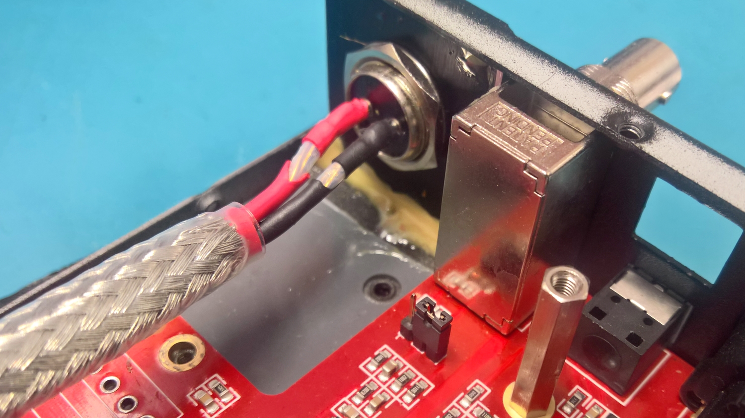
First photo is the instuction page from the mutec instructions:  This shows the 50 ohm through termination on the end of my clock lead. I haven't tried this yet..  |
|
optical
Moderator
BIG STAR
Be Excellent To Eachother
Posts: 1,623 
|
Post by optical on Mar 28, 2023 10:15:38 GMT
First photo is the instuction page from the mutec instructions: This shows the 50 ohm through termination on the end of my clock lead. I haven't tried this yet.. Alan . . . have you tried the clock using the TTL output as oposed to the Sine . . . .  |
|
|
|
Post by firebottle on Mar 28, 2023 10:25:07 GMT
I am using the TTL output. I tried the sine output briefly and cound't detect a difference on a quick listen.
|
|
optical
Moderator
BIG STAR
Be Excellent To Eachother
Posts: 1,623 
|
Post by optical on Mar 28, 2023 10:44:15 GMT
I am using the TTL output. I tried the sine output briefly and cound't detect a difference on a quick listen. Oh yes I see, got them mixed up. I too have tried both and seem to prefer the Sine by a hair . . . although I need to do some more testing. |
|
|
|
Post by misterc on Mar 28, 2023 10:57:09 GMT
First photo is the instuction page from the mutec instructions:  This shows the 50 ohm through termination on the end of my clock lead. I haven't tried this yet.. 
Here you go this is it
|
|
Bigman80
Grandmaster
 The HiFi Bear/Audioaddicts/Bigbottle Owner
Posts: 16,398
Member is Online
|
Post by Bigman80 on Mar 28, 2023 10:58:26 GMT
First photo is the instuction page from the mutec instructions:  This shows the 50 ohm through termination on the end of my clock lead. I haven't tried this yet.. 
Here you go this is it
Cool. Thanks T |
|
|
|
Post by bencat on Mar 28, 2023 11:01:49 GMT
Alan great post can I just check with you my clock has bnc output not as yours . I am ordering a fully specified 50 ohm bnc to bnc cable . After I take the 75 ohm plug out of circuit would I still need the 50 ohm through termination of could I just attach the 50 ohm cable as it is ?
|
|
|
|
Post by misterc on Mar 28, 2023 11:03:19 GMT
Alan great post can I just check with you my clock has bnc output not as yours . I am ordering a fully specified 50 ohm bnc to bnc cable . After I take the 75 ohm plug out of circuit would I still need the 50 ohm through termination of could I just attach the 50 ohm cable as it is ? YES
|
|
